What Is Plastic Mold Manufacturing and How Does It Work?
Plastic mold manufacturing is the controlled process of designing and producing molds that shape molten plastic into repeatable parts. It supports products found in medical devices, automotive interiors, electronics, packaging, and household equipment. The mold may look like a steel block, but its internal details determine quality, speed, and cost.
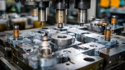
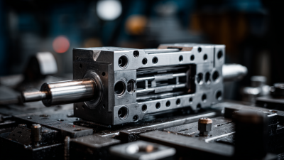
As injection-molding consultant John Bozzelli explains, “The mold is the heart of the injection molding process.” That statement reflects practical experience. A mold contains cavities, cores, cooling channels, gates, ejector pins, and vents. Each feature has a purpose. The cavity creates the external shape. The core forms internal spaces. Cooling channels remove heat before the part is ejected.
The workflow begins with product analysis and mold-flow planning. Engineers review wall thickness, shrinkage, draft angles, tolerances, and material behavior. Designers then create the mold model and select suitable steel or aluminum. Machining, electrical discharge machining, polishing, assembly, and trial molding follow. During testing, technicians inspect flash, sink marks, weld lines, warpage, and incomplete filling.
Small details matter.
For example, an uneven cooling channel can bend a flat cover after ejection. A poorly positioned gate can leave a visible mark on a consumer product. These problems may require steel changes, process adjustments, or a redesigned feature.
Plastic mold manufacturing is highly precise, but it is not perfectly predictable. Material batches vary. Production conditions drift. Even experienced teams can miss a hidden risk during early design reviews. Reliable results therefore depend on measured trials, documented inspections, and cooperation between designers, mold makers, and production engineers. This guide examines how the process works, where common failures begin, and how careful decisions improve mold performance.
What Plastic Mold Manufacturing Is and Why It Matters
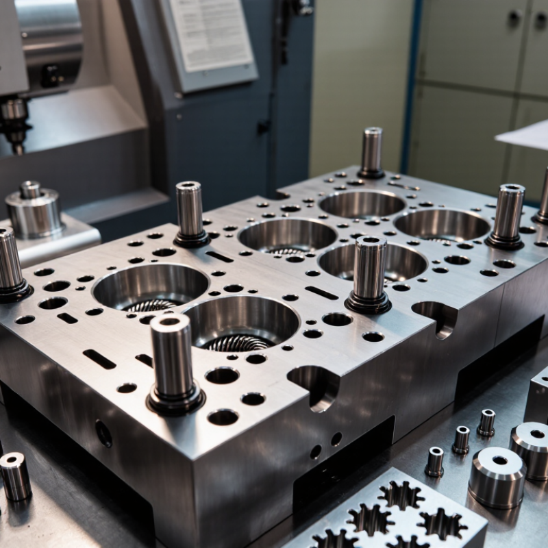
Plastic mold manufacturing is the process of creating precise tools that shape molten plastic into finished parts. It turns a digital design into a repeatable production method. Engineers study the part geometry, plastic behavior, cooling needs, and ejection points before cutting the mold. A typical mold contains a cavity, core, runners, gates, and cooling channels. Each feature affects filling speed, surface quality, and dimensional accuracy.
The process usually includes design, machining, polishing, assembly, and trial production. Machinists may use computer-controlled equipment to form steel or aluminum components. Trial shots reveal problems such as short fills, sink marks, flash, or uneven cooling. Small changes to gate size or temperature can improve the result.
This work matters because reliable molds reduce waste, stabilize quality, and support predictable production costs. A well-built mold can also protect part function, especially when tight measurements are required. Poor mold decisions can create defects that no later inspection fully solves.
From practical experience, communication between designers, toolmakers, and production teams is essential. A perfect first mold is rare. Review remains necessary.
Tips:
Check draft angles before machining. Confirm shrinkage data with material suppliers. Inspect cooling channels carefully. Record trial results, even when they seem minor. A small note today may prevent repeated defects later. Do not assume a successful sample guarantees long-term performance; wear, maintenance, and production speed still need evaluation.
How a Plastic Mold Is Engineered and Manufactured
Plastic mold manufacturing begins with engineering, not machining. A designer reviews wall thickness, draft angles, parting lines, gates, and expected shrinkage. The goal is steady filling without sink marks or trapped air. This matters in a large market: Grand View Research estimated the global plastic injection molding market at about USD 178.6 billion in 2023.
A mold maker then converts the approved design into cavity and core geometry. CNC milling creates most surfaces, while electrical discharge machining forms sharp ribs and deep details. Cooling channels are positioned near hot areas, but not always evenly. That mistake can cause warpage. Mold steel is selected according to production volume, resin abrasiveness, and required surface finish. Polishing follows machining, often under magnification. Small scratches may become visible on every molded part.
The mold enters a trial stage, where technicians inspect fill balance, dimensions, flash, and ejection marks. Measurement equipment compares samples with the CAD model and relevant ISO 20457 tolerance guidance. PlasticsEurope reported global plastics production of 400.3 million tonnes in 2022, showing why repeatable tooling remains important. Yet perfect prediction is unrealistic. Resin batches vary, and cooling behavior can surprise experienced teams. A reliable process leaves room for adjustment. Final changes may include gate resizing, vent cleaning, or steel-safe polishing. Tiny corrections matter.
The Step-by-Step Plastic Injection Molding Process
Plastic mold manufacturing turns a product design into a reusable production tool. The process starts with a 3D model and a careful review of wall thickness, corners, and draft angles. Engineers then select mold steel or aluminum, cut the cavity, and add cooling channels and an ejection system. Good design matters. Even a tiny sharp corner can create stress or slow production.
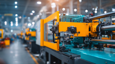
At the molding machine, plastic pellets enter a heated barrel and soften gradually. A rotating screw mixes the material and pushes it forward. The mold closes tightly, and molten plastic fills its cavity under controlled pressure. Holding pressure reduces shrinkage while cooling channels remove heat. Once the part becomes stable, ejector pins release it from the mold. Operators inspect dimensions, surface finish, and possible marks. Small defects still happen. In practice, the first trial often reveals details that drawings cannot predict. Teams may adjust temperature, pressure, cooling time, or venting before production becomes consistent.
Tips: Keep the material dry before molding. Moisture can cause bubbles or weak surfaces. Check mold alignment regularly. Record every machine setting and inspection result. A short trial run is useful, but it should not replace proper testing. When defects appear, investigate the cause instead of hiding the symptom.
Typical Plastic Injection Molding Cycle
This chart shows representative time ranges for the main steps in a thermoplastic injection molding cycle. Cooling usually takes the longest because the part must solidify sufficiently before ejection. Actual times vary with material, wall thickness, mold design, and machine settings.
Quality Control, Common Defects, and Production Improvements
Plastic mold manufacturing begins with a steel or aluminum mold designed around the product’s shape, material, and expected production volume. Skilled technicians review wall thickness, draft angles, cooling channels, and ejection points before machining starts. Small details matter. A poorly placed gate can create visible flow marks, while uneven cooling may cause warping or sink marks. During trial molding, operators record pressure, temperature, cycle time, and part weight. These measurements provide stronger evidence than visual inspection alone.
Quality control continues throughout production. Inspectors use gauges, coordinate measuring equipment, and surface checks to compare parts with approved specifications. Common defects include short shots, flash, weld lines, burn marks, dimensional drift, and trapped air. Each defect needs a different response. Vent cleaning can reduce burn marks, while adjusting injection speed may improve weld lines. Mold maintenance also includes polishing, lubrication, corrosion checks, and confirming ejector movement. Neglecting these tasks often creates repeated defects. That sounds minor, but it can increase scrap quickly.
Production improvements should be tested carefully rather than applied by guesswork. A controlled change to cooling time, mold temperature, or holding pressure can reveal the real cause. Experienced teams document every adjustment and compare results across several cycles. Still, even a strong checklist can miss a defect caused by material variation or operator fatigue. That weakness deserves review. Reliable manufacturing depends on traceable records, stable processes, trained inspection staff, and honest communication between design and production teams.