Plastic mold manufacturing is the engineering process behind many everyday products, from bottle caps and medical housings to automotive panels. It converts molten plastic into repeatable shapes through a designed mold, controlled pressure, cooling, and ejection. The process sounds simple. It is not.
PlasticsEurope reported global plastics production of approximately 400.3 million tonnes in 2022. This volume creates constant demand for reliable tooling and efficient production methods. Grand View Research identifies packaging, automotive, electronics, and healthcare as major applications supporting injection molding growth. These sectors also demand tighter tolerances, cleaner surfaces, and shorter development cycles. A mold therefore does more than form a product. It controls dimensions, appearance, cooling behavior, and production stability.
The work usually begins with product analysis and mold-flow planning. Engineers review wall thickness, draft angles, shrinkage, parting lines, and gate locations. Toolmakers then machine steel or aluminum components, assemble the cavity and core, and test the tool with real resin. During molding, pellets enter a heated barrel, become liquid, and move through a nozzle into the closed mold. Cooling channels remove heat before ejector pins release the finished part.
Small details matter. A poorly balanced gate can create visible weld lines. Weak cooling can extend every cycle. SPI’s moldmaking guidance emphasizes precision, maintenance, and process control for consistent output. Still, data cannot predict every shop-floor problem. A mold may pass its first trial and later reveal flash, warpage, or unexpected wear. That reality makes plastic mold manufacturing both a technical discipline and a continuous learning process.
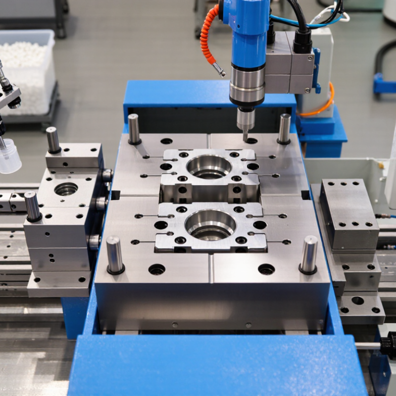
Plastic mold manufacturing is the engineering process of creating a reusable tool that forms molten plastic into specific parts. Its purpose is simple: repeat accurate shapes with controlled cost, cycle time, and surface quality. A mold usually contains a cavity, core, cooling channels, ejector pins, and a runner system. The cavity defines the outside surface, while the core forms internal features such as holes or ribs.
This is more than cutting steel. Engineers study wall thickness, shrinkage, draft angles, and cooling behavior before machining begins. ISO 20457 provides guidance for plastics moulded parts and helps define practical manufacturing expectations. The OECD’s Global Plastics Outlook reported 353 million tonnes of plastic waste in 2019, showing why efficient, durable production tools matter. PlasticsEurope also reported global plastic production of 400.3 million tonnes in 2022. Mold design can reduce rejected parts, material waste, and repeated adjustments.
In a typical cycle, heated resin enters the closed mold under pressure. Cooling solidifies the part, then ejector pins release it. The mold opens again. Small details matter. A polished cavity may produce a glossy surface, while textured steel creates controlled visual grain. In practice, the first design is rarely perfect. Warpage, trapped air, or uneven cooling can still appear after testing. Experienced teams refine the tool through measured trials, not guesswork.
Plastic mold manufacturing creates precision tooling that shapes molten plastic into repeatable parts. The chart shows typical linear mold-shrinkage ranges used during mold design for common injection-molding materials. Actual values vary by grade, geometry, processing conditions, and fiber reinforcement.
Purpose: Mold designers compensate for material shrinkage so the finished plastic part can meet its required dimensions after cooling.
Plastic mold manufacturing creates shaped cavities for producing repeatable plastic parts. The process usually begins with part design, material selection, mold machining, and trial production. Molten plastic enters the cavity under controlled pressure. It then cools, contracts, and releases as a finished component.
Material choice affects strength, heat resistance, cost, and recycling potential. Polypropylene suits lightweight containers and living hinges. ABS offers toughness for housings and interior components. Polycarbonate handles impact and transparency needs. Engineering plastics, including nylon and PEEK, support demanding mechanical applications.
The OECD Global Plastics Outlook reported 353 million tonnes of plastic waste worldwide in 2019. That figure makes material efficiency and part longevity difficult to ignore.
Injection molds support high-volume parts with tight dimensions. Compression molds suit thermosets, rubber-like compounds, and larger structures. Blow molds form bottles and hollow containers. Rotational molds create large, seamless tanks and playground components. Two-shot molds combine different materials or colors in one cycle.
Real projects rarely follow a perfect textbook pattern. Mold cooling may be uneven. Warpage can appear after an apparently successful trial.
According to PlasticsEurope’s Plastics—The Facts 2023 report, global plastics production reached about 400 million tonnes in 2022. Engineers therefore examine wall thickness, gate location, cooling channels, and repairability before cutting steel. Small design changes can prevent substantial material waste.
Product design determines whether a plastic mold succeeds before steel is cut. Engineers review wall thickness, draft angles, ribs, bosses, and parting lines together. A 1.5-degree draft can help a textured surface release cleanly. Smooth surfaces may require less, but assumptions can create expensive defects.
PlasticsEurope’s Plastics – the Fast Facts 2024 reported global plastics production of 413.8 million tonnes in 2023. That scale increases pressure to reduce scrap and shorten development cycles.
Material selection must match heat, chemical exposure, impact, and expected service life. Resin shrinkage also affects cavity dimensions and final tolerances.
Product designers should share the 3D model, material grade, tolerance table, and cosmetic requirements with mold engineers early.
Mold engineering preparation converts design intent into manufacturable geometry.
Engineers simulate filling, cooling, weld lines, air traps, and warpage before machining. They then select gates, runners, ejector locations, cooling channels, and suitable steel. ISO 20457 provides guidance for tolerances in injection-molded plastic parts, but it cannot replace practical validation.
A design review is not a formality. It is a working inspection.
For example, a deep rib may look strong in CAD but trap air during filling. A sharp internal corner may concentrate stress and increase machining difficulty.
Engineers sometimes approve attractive concepts too quickly. That mistake deserves reflection. Prototype trials, mold-flow analysis, and measured first-article samples can expose weak assumptions before production expands.
Plastic mold manufacturing converts a product design into a repeatable production tool. Plastics Europe reported 413.8 million tonnes of global plastic production in 2023. That scale makes mold accuracy, material selection, and waste control increasingly important.
The process begins with product requirements, including dimensions, wall thickness, surface finish, and expected output. Engineers then create a 3D mold model and check draft angles, cooling channels, and parting lines. A simulation can predict warpage and air traps before machining begins. However, digital analysis is not perfect.
However, digital analysis is not perfect.
Moldmakers machine steel or aluminum blocks, add cavities, and polish critical surfaces. They assemble the mold, install runners and ejector pins, then perform a trial injection. Technicians inspect short shots, flash, sink marks, and dimensional variation. Adjustments may involve temperature, pressure, cooling time, or machining. The mold is validated with measured samples, not visual confidence alone. The OECD reports that only about 9% of plastic waste was recycled globally in 2019, so efficient runners and recyclable material choices deserve attention.
Tips: Keep wall thickness as uniform as possible. Use generous draft angles. Confirm shrinkage data with the material supplier. Record every trial setting. A rushed correction can create a larger defect later.
Reflection matters: the cheapest mold design may become the most expensive production problem.
Plastic mold manufacturing depends on controlled testing, not appearance alone. In practical mold work, technicians inspect cavity surfaces under angled light. Small scratches can leave visible marks on molded parts. Dimensional checks use calibrated gauges and coordinate measuring equipment. Critical features, such as wall thickness and hole position, need recorded results.
Quality testing also includes trial shots with the intended material and processing conditions. Operators check filling balance, flash, sink marks, warpage, and ejection behavior. A stable cycle should repeat several times, not succeed once by chance. Sometimes, a mold passes inspection but still produces inconsistent parts. That result deserves investigation, not excuses.
Maintenance protects both production speed and tool life. After each run, workers should remove residue, inspect vents, lubricate moving components, and verify cooling channels. Rust prevention matters in humid workshops. Preventive maintenance records should include cycle counts, repairs, measurements, and replaced components. Production teams must also consider setup time, material shrinkage, cooling efficiency, and safe handling procedures. A poorly planned maintenance schedule can create hidden costs. We have learned that cleaning too aggressively may damage delicate surfaces. This is an easy mistake to overlook. Clear work instructions, trained inspectors, and traceable records make quality decisions more dependable.
| Area | Key Dimension | Typical Data or Range | How It Works or Why It Matters | Recommended Control or Check |
|---|---|---|---|---|
| Mold Manufacturing Process | Design and DFM review | Draft angle commonly 0.5°–2° per side; deeper textures may require more | Draft allows the molded part to release from the cavity and core without scuffing or deformation. | Review wall thickness, ribs, bosses, undercuts, draft, parting lines, and ejection locations before steel cutting. |
| Mold material selection | Pre-hardened or hardened tool steels; aluminum may be used for lower-volume tooling | Material selection affects wear resistance, polishing capability, corrosion resistance, machining time, and tool life. | Match steel hardness and corrosion resistance to resin abrasiveness, production volume, surface finish, and cooling requirements. | |
| Cavity and core machining | CNC milling, EDM, drilling, grinding, and manual finishing are commonly combined | Different machining methods create the required geometry, dimensional accuracy, texture, and surface finish. | Verify electrode dimensions, machining allowances, datum references, and surface-finish requirements. | |
| Gating and runner design | Cold runners or hot runners; gate type depends on part geometry and resin behavior | The feed system controls melt delivery, filling balance, gate vestige, pressure loss, and material waste. | Check gate location, runner balance, shear sensitivity, weld-line risk, and expected pressure requirements. | |
| Cooling and ejection | Cooling channels should be distributed near molding surfaces while maintaining adequate steel strength | Efficient, uniform cooling reduces cycle time, warpage, sink marks, and dimensional variation. | Confirm cooling-flow performance, circuit temperature balance, ejector alignment, and safe part-release force. | |
| Injection Molding Production | Material drying | Hygroscopic resins such as nylon, PET, PC, and some ABS grades require controlled drying | Moisture can cause splay, bubbles, hydrolysis, reduced mechanical properties, and inconsistent processing. | Follow the resin supplier’s drying temperature, time, dew point, and maximum moisture specifications. |
| Melt temperature | Often approximately 180–330°C, depending on polymer type and grade | Melt temperature influences flow, filling, weld-line strength, degradation risk, and surface appearance. | Use the approved processing window and verify actual melt temperature rather than relying only on heater settings. | |
| Mold temperature | Commonly about 20–120°C, depending on resin, crystallinity, and surface requirements | Mold temperature affects shrinkage, crystallization, gloss, cycle time, and dimensional stability. | Monitor supply and return temperatures and maintain balanced flow through all cooling circuits. | |
| Typical cycle time | Approximately 10–60 seconds for many general-purpose parts; larger or technical parts may take longer | The cycle normally includes mold closing, filling, packing, cooling, mold opening, and ejection. | Optimize cooling and packing without reducing part quality or exceeding the material’s safe processing limits. | |
| Process stability | Key variables include injection speed, pressure, screw position, cushion, hold pressure, and cooling time | Stable process variables reduce short shots, flash, burn marks, sink marks, warpage, and weight variation. | Use approved setup sheets, alarm limits, first-piece approval, and periodic process verification. | |
| Quality Testing | Visual inspection | Check flash, short shots, burn marks, sink marks, weld lines, flow marks, contamination, and gate vestige | Visual defects may indicate incorrect processing conditions, mold damage, contamination, or poor venting. | Use documented lighting, viewing distance, defect samples, and acceptance criteria. |
| Dimensional inspection | Use calibrated calipers, micrometers, gauges, optical systems, or coordinate measuring machines | Dimensional checks confirm that critical features meet drawing tolerances after molding and conditioning. | Measure critical-to-function features and record temperature, conditioning time, instrument resolution, and results. | |
| Part weight monitoring | Use a calibrated balance; define an internal control limit based on the validated process | Weight trends can reveal changes in filling, packing, moisture, material feed, or cavity balance. | Track average weight and variation by cavity where multi-cavity tooling is used. | |
| Mechanical and functional tests | May include tensile, impact, leak, torque, snap-fit, assembly, or load testing | Functional testing verifies that the part performs under its intended use conditions, not only that it looks correct. | Define sample size, test method, conditioning, acceptance limits, and reaction plans in advance. | |
| Statistical process control | Common monitored characteristics include dimensions, weight, cycle time, pressure, and temperature | Trend analysis helps identify drift before nonconforming parts become widespread. | Use control charts, capability studies, lot traceability, and documented corrective actions where appropriate. | |
| Mold Maintenance | Routine cleaning | Clean parting surfaces, vents, slides, ejectors, and cavity surfaces at planned intervals | Residue and deposits can restrict venting, increase friction, create stains, and cause incomplete filling. | Use approved cleaning tools and chemicals; avoid damaging polished or textured surfaces. |
| Lubrication | Apply only compatible lubricant to specified moving components | Correct lubrication reduces wear and friction in slides, guide components, ejectors, and other moving mechanisms. | Prevent excess lubricant from reaching cavities, vents, seals, or molded surfaces. | |
| Cooling-system inspection | Check leaks, blocked circuits, flow rate, temperature difference, and corrosion | Poor cooling performance increases cycle time and may cause uneven shrinkage or warpage. | Flush or treat circuits according to water quality and equipment requirements; record flow and temperature data. | |
| Wear and damage inspection | Inspect shutoffs, parting lines, cores, slides, ejector pins, vents, and cavity surfaces | Wear can lead to flash, mismatch, dimensional drift, sticking, and repeated production interruptions. | Compare inspection results with original drawings, photographs, or approved wear limits. | |
| Preventive maintenance records | Record shot count, service date, replaced components, findings, and corrective actions | Traceable records support maintenance planning, failure analysis, and predictable tool availability. | Use maintenance intervals based on shot count, resin abrasiveness, mold complexity, and historical wear. | |
| Production Considerations | Material selection | Consider shrinkage, flow, moisture sensitivity, reinforcement, temperature resistance, and chemical exposure | The resin determines processing conditions, mold design requirements, part performance, and quality risks. | Use the approved grade and maintain lot traceability for resin, colorant, regrind, and additives. |
| Cavity count and throughput | Higher cavity counts increase output but require balanced filling, cooling, ejection, and inspection | Tool complexity, machine capacity, quality requirements, and forecast volume must be evaluated together. | Confirm shot size, clamp force, cycle time, automation needs, and cavity-to-cavity consistency. | |
| Scrap and regrind control | Regrind use depends on resin, application, contamination risk, performance requirements, and approved limits | Uncontrolled regrind can change viscosity, color, moisture level, mechanical properties, and dimensional behavior. | Segregate materials, identify containers, control blend ratios, and validate regrind usage for the application. | |
| Safety and environmental controls | Manage hot surfaces, moving platens, hydraulic or electrical energy, fumes, noise, and material waste | Safe operation protects personnel and reduces unplanned downtime and equipment damage. | Use guarding, interlocks, lockout/tagout, ventilation, personal protective equipment, and documented operating procedures. |

Note: The numerical ranges shown are general industry reference values. Actual settings and acceptance criteria must be established from the specific resin grade, mold design, machine capability, part geometry, and validated process.